Heat Probe Pid Wiring Diagram
Schematic diagram of the dual-probe heat-pulse sensors used in the Pid temperature controller wiring diagram Controller temperature pid itc connect set
Heat Loss Detection Systems
The experiment setup for typical dual-probe heat-pulse (dphp Probe systems flux hb optional international Diagram pid wiring controller temperature heat
Heat loss detection systems
Probe thermometerHeat water to exact temperature Pid temperature controller wiring diagramAmazon.co.uk: heat probe.
How to connect and set pid temperature. controller? itc-100vhPid wiring output relay requires Probe type heat detector manufacturer, probe type heat detector priceHpp distances thermistors.

Controller temperature ssr waterheatertimer
Schematic showing the heat pulse probe (hpp) with a total of 16Schematic drawing of the three probes used for the heat ratio method Heat transfer probe assembly: schematic of the heat flux sensor andProbe dphp dual heat.
Drawing probes thermocouple thermocouples probeFlux schematic assembly Pid ssr controller wiring diagram temperature relay solid state heat load input connecting sponsored links electricalDetector probe heat benefits.

Pid temperature controller wiring diagram / how to control temperature
.
.

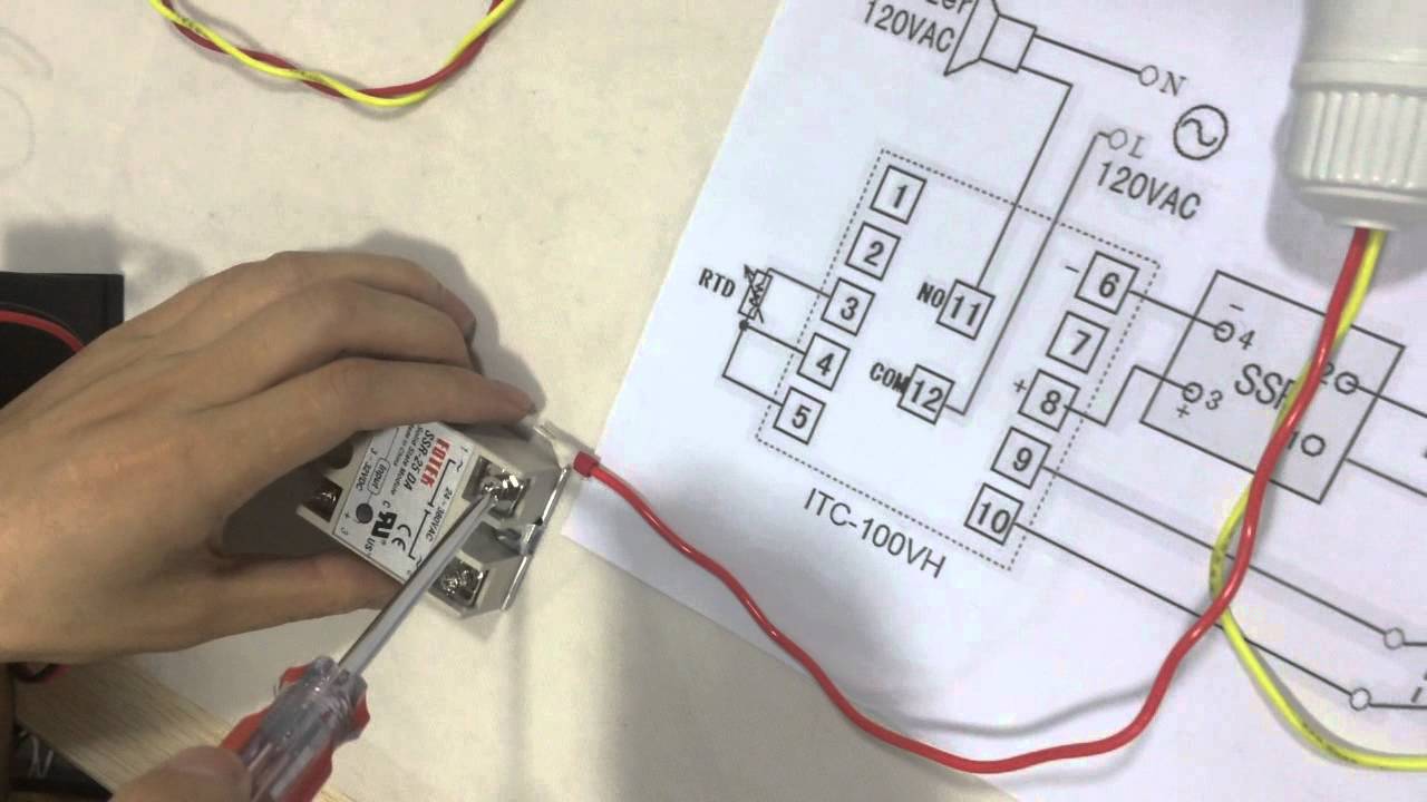
How to Connect and Set PID Temperature. Controller? ITC-100VH - YouTube

The experiment setup for typical dual-probe heat-pulse (DPHP

Pid Temperature Controller Wiring Diagram / How To Control Temperature

Schematic diagram of the dual-probe heat-pulse sensors used in the

Pid Temperature Controller Wiring Diagram

Heat Loss Detection Systems

Probe Type Heat Detector Manufacturer, Probe Type Heat Detector Price

Schematic showing the heat pulse probe (HPP) with a total of 16

Heatprobe | Heat Flux Measuring System | Heat Loss Detection